Foreword
The following mounting instructions apply to all ball bearing rail guides. However, some detailed specifications can be provided with the product descriptions in a timely manner.
Linear guides from the DHM pro line are high-quality products. We recommend the utmost care and attention when assembling the parts to avoid damage.
Linear guides DHM pro have the same load capacity in radial, reverse radial, and lateral directions. They are designed for maximum accuracy when mounted on plates and bases suitable for their use. Each rail has ground reference surfaces. On each side of the skid there are ground reference surfaces. This is to facilitate installation and calibration of the entire system; in fact, the operator can use these surfaces as a reference for monetizing components.
Linear rail assembly instructions: warnings
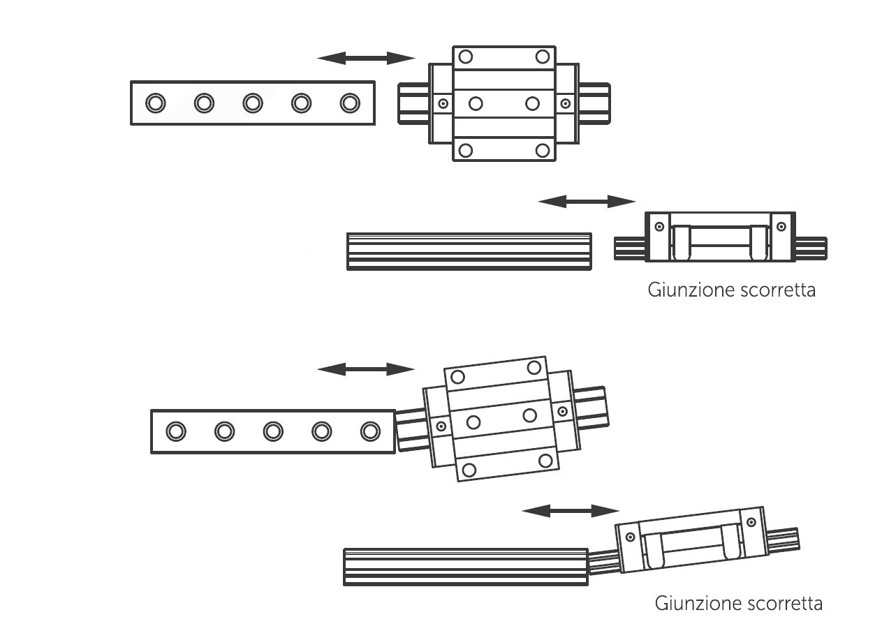
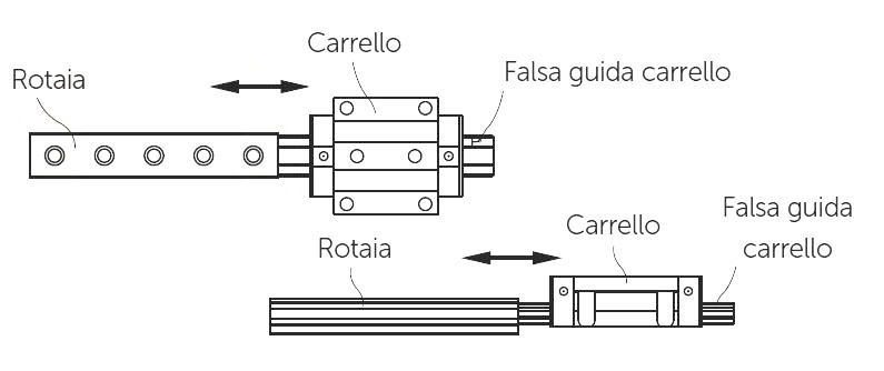
The runner recirculation face must not be subjected to shocks. Any shocks may affect the recirculation of the balls and cause sliding anomalies. The balls do not fall out of the linear guides DHM pro when disassembled from the rails because the carriages are equipped with special stops. However, balls may fall out if you quickly disassemble the carriages from the rail or insert the rail into the carriage at an angle. When handling the rail, therefore, always keep it in a horizontal position.
Disassemble and assemble the carriages carefully. Do not disassemble parts arbitrarily, to avoid penetration of foreign matter into the carriage and decrease the accuracy of the rail.
Accuracy and radial clearance are only guaranteed when using carriages and rails from the same kit, or from the same batch. We therefore do not recommend swapping carriages and rails from the original combinations.
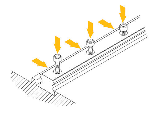
The accuracy of the linear rails is guaranteed after the rail has been mounted, after the screws have been fastened to the rail and the rail has been pushed onto the reference plane. To ensure the linearity of the rail, tighten the fixing screws in sequence.
Lubrication and maintenance
Before shipping, DHM pro rails are given an oil coating to protect them from corrosion. We recommend removing the oil before moving or using the slides.
Basic lubrication should be carried out before commissioning by proceeding in several ways, here is the recommended one:
- grease the skid with an appropriate amount of lubricant (use the hole provided for lubrication-use a syringe for miniature models such as MGN9 and MGN12)
- move the skid back and forth at least three times the length of the skid
- repeat the operations of the previous steps two more times
- check whether the lubricant layer is visible on the rail
As lubricant we recommend a grease according to DIN 51825 K2K (lithium grease) for normal loads.
Caution. Greases with solid additives such as MoS2 or graphite should not be used.
Lubrication is a key element in order to ensure proper operation of recirculating ball systems. So after the guides are first put into use, it must be carried out at periodic intervals.
Proper lubrication leads to benefits that extend the life of the entire linear system. Especially it leads to a reduction in the system of:
- Corrosion
- Friction
- Wear
- Impurities
It is recommended that the rails be cleaned before lubrication. To ensure that the runner does not leak out during these maneuvers one can help by putting a clamp through the last holes.
It is recommended to lubricate the rails and bearing balls with grease. Then proceed by coating the entire rail with a thin layer of grease to prevent oxidation.
The relubrication interval depends on the type of operating environment, type of load, frequency of use, and distances traveled by the skid.
The operating environment is defined as all factors external to the system, such as small chips, material
removed by abrasion, surrounding temperatures, humidity. By load type, on the other hand, we mean those factors that directly affect the system, such as shock, types of torsional loading, and vibration.
We recommend a maintenance and lubrication frequency of 6 months, or every 3 if usage is heavy or distances traveled are long. Depending on the above conditions if the grease deteriorates or becomes contaminated more quickly, it is necessary to reduce the lubrication interval according to the needs of the system.
In general, the conditions to be evaluated to schedule maintenance and lubrication of the linear system are:
- Vibration
- High operating temperatures
- Presence of condensation or any splashing of water
- Presence of special substances (vapors, acids, hydrocarbons)
- Working stroke in a short section of rail
- High dynamics of operation
Mounting configurations: examples of typical mounting positions
Mounting position depends on machine requirements and load direction. The accuracy of the rail depends on the flatness and straightness of the installation surfaces. Since it is not a self-supporting element, it in fact adapts to the structure to which it is applied.
Thus rails mounted on an improperly machined surface may have larger tolerances in terms of straightness.
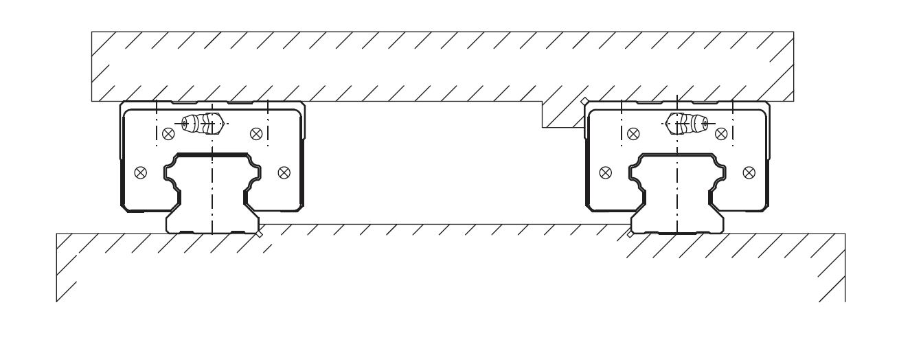
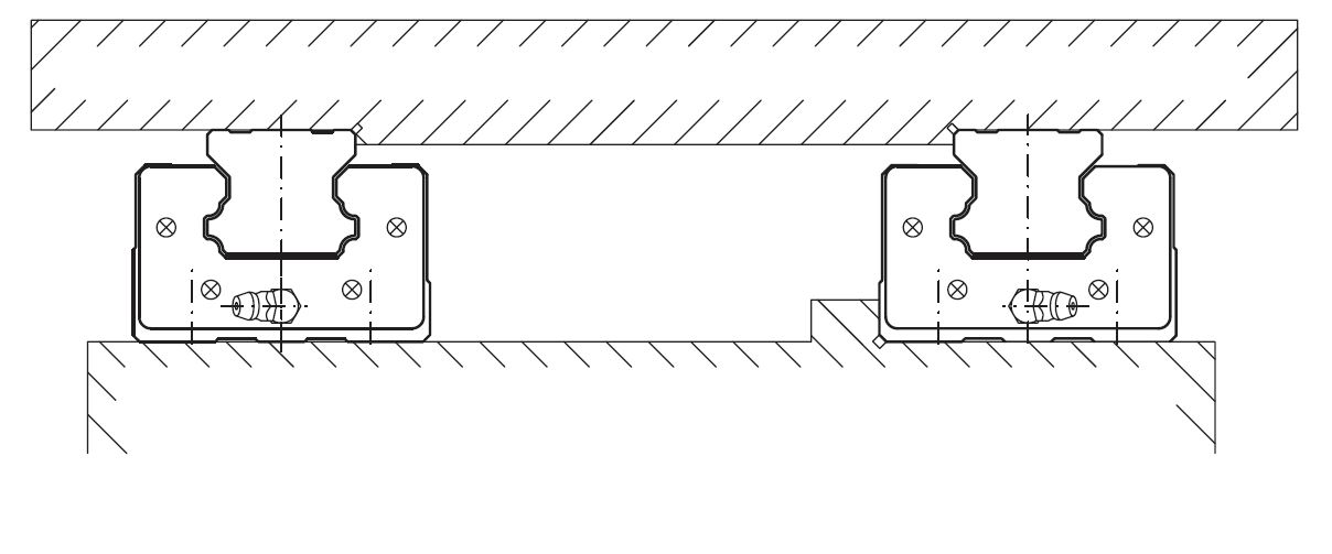
Below we see some examples of typical mounting positions of linear ball bearing rails on rails.
Single rail with mounting based on the reference side
Pair of rails with movable carriage
Pair of rails with fixed carriage
Pair of outer rails
Pair of inner rails
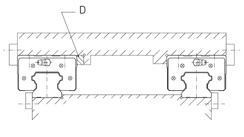
Mounting with all reference surfaces locked
D=thickness
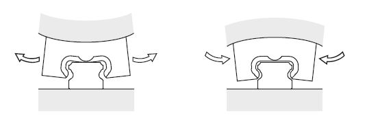
We urge caution because the carriages may deform due to the flatness of the mounting surface. We recommend the flatness of the mounting surface 5μ. Deformation of the carriage may cause backlash that could provide lower/upper preload and lead to slip defects.
Mounting Procedures.
There are a few recommended installation methods, depending on the required precision of movement and the amount of shock or vibration to which the system is subjected.
-
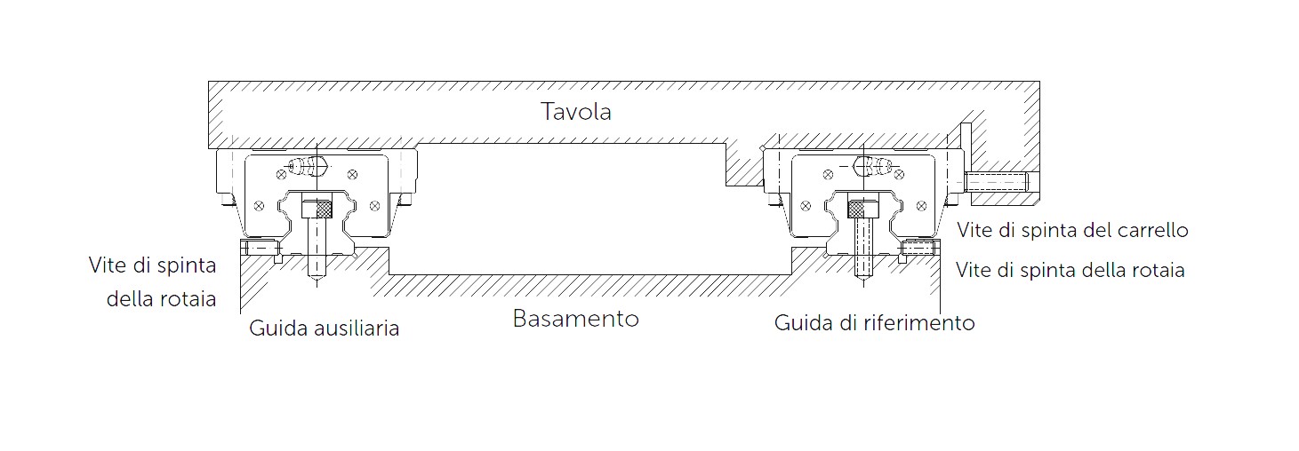
Installation of rails with reference guide and adjusting screw
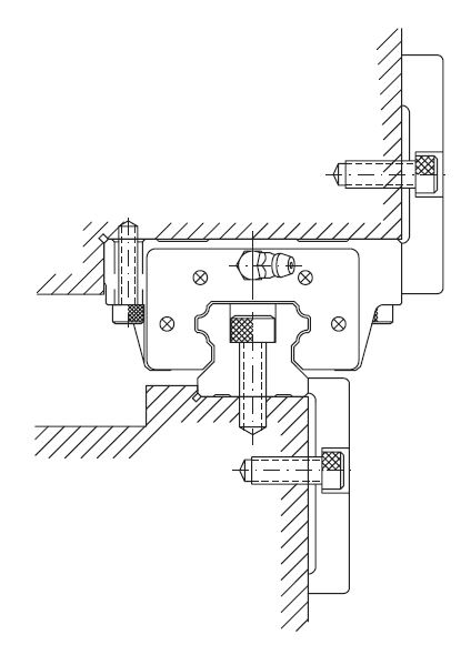
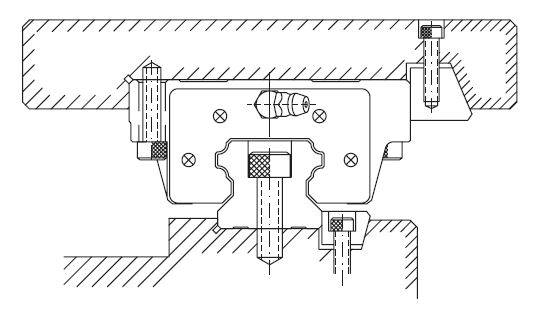
In machines subjected to severe vibration and shock or lateral forces, displacement of the rails or carriages may occur. To avoid this problem and increase rigidity and precision of movement, we recommend assembling the linear rail with reference planes and clamps on both sides.
We suggest the following four assembly methods:
| Mounting with locking plate | Mounting with push screws |
 |
 |
| Mounting with locking wedge |
Mounting with roller |
 |
 |
Let's see here how to install the rails:
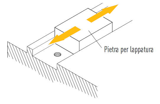
a. Before installation, remove dirt from the mounting surface of the machine. Go over the mounting surface with a lapping stone if necessary. The ideal case is to work with ground mounting surfaces.
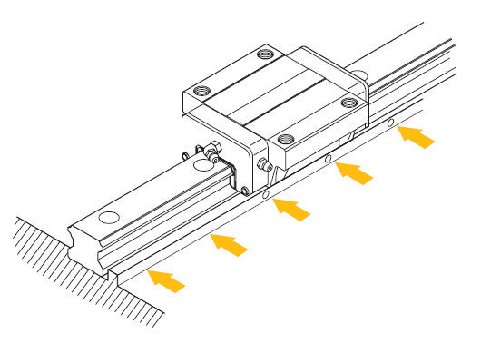
b. Lay the rail on the base and bring it into contact with the base strike.
c. Check that the thread of the screw fits properly into the mounting hole.
d. Tighten the adjusting grub screws in sequence to ensure optimum contact between the rail and the basement striker.
e. Tighten the setscrews in sequence (for special applications depending on the crankcase material, the torque wrench can be used to tighten them all with the same force)
f. Install the rest of the linear guide in the same way.
See here how to install the carriages:
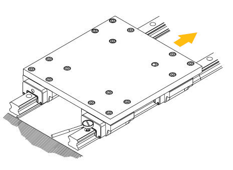
a. Gently place the plate on the runners. Then tighten the carriage fixing screws tentatively.
b. Push the carriages against the plate striker and align it by fastening the adjusting screws.
c. To fix the plate evenly, tighten the fixing screws on the primary reference rail and the secondary rail by proceeding in sequence from 1 to 4.
2. Installation of rails with reference plate without thrust screws
To ensure parallelism between the secondary (or auxiliary) rail and the primary (reference) rail without using set screws, it is advisable to install the rails by one of the following methods.
The procedure shown above can be followed to install the rails.
Here are the directions for installing the secondary rail on the side of the primary rail:
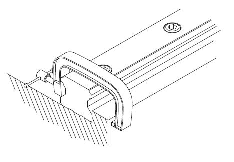
After arranging the rail on the basement mounting surface, fasten the fixing screws provisionally. Using a clamp, push the rail against the side strike of the basement. Then proceed by tightening the fixing screws in sequence applying the torque according to the material.
For installing the rail on the side of the subrail, however, 4 different methods can be used.
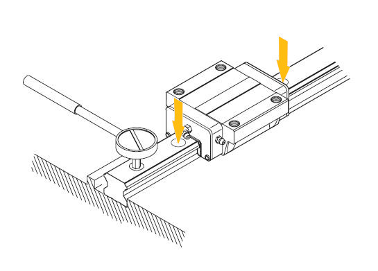
a. Method based on dial indicator
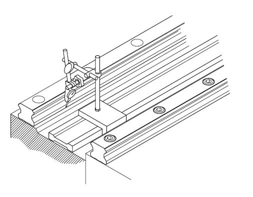
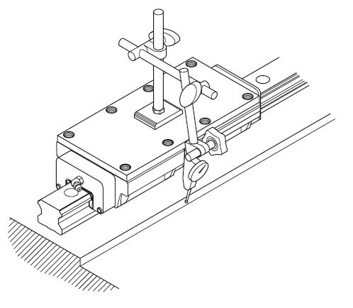
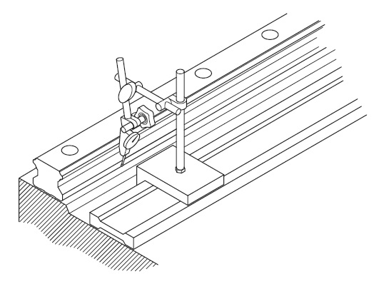
Using a dial indicator, place a control line between the rails, parallel to the side strike of the rail on the primary rail side. When the rail on the side of the secondary rail is parallel to that of the primary rail, tighten the set screws sequentially from one end of the rail to the other.
b. Table-based method
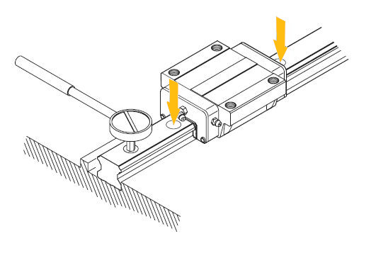
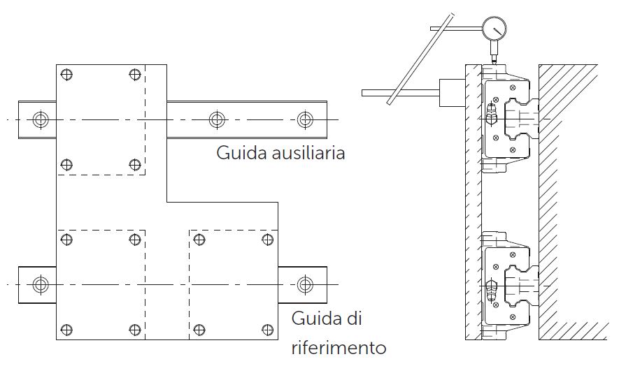
Fasten the two carriages on the primary rail side to the board. Secure one carriage to the table on the secondary rail side tentatively. Then attach a dial indicator to the surface of the table and bring it into contact with the carriage side of the secondary rail. Move the table from one end of the rail to the other and align the secondary rail parallel to the primary rail. Fasten the screws in sequential order.
c. Method based on the reference rail
If the reference rail is properly stopped, attach both carriages of the reference rail to the table
reference guide and one of the two of the auxiliary guide. While moving the table from one end of the rail to the other, fasten the screws of the auxiliary rail.
d. Method based on mounting jig
A template (mounting jig) can be used to check that the secondary rail is in the correct position. Then fasten the screws in sequence by applying the specified torque according to the material.
3. Installation of rails with reference plane and thrust screw
To ensure parallelism between the secondary rail and the primary rail if there is no reference plane, the method explained below should be used.
On the other hand, follow the procedure given above to install the carriage.
a. Alignment to a temporary striker
Attach two trolleys closely together using the plate. Use the striker available on the plinth to align the rail on both ends. Move the sliders and tighten the fixing screws in sequence, applying the specified torque.
b. Alignment to a control line.
A dial indicator and a control line can be used to align the rail from one end to the other. Then tighten the fastening screws in sequence.
Then proceed with the directions above for installing the secondary rail on the side of the primary rail.
Learn about the linear guides and skids in the DHM pro line in the dedicated section.
Need more information?
Check the product sheet for all the technical information, or CONTACT US.


