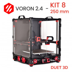
Voron 2.4 STEP 8: original electronics Duet3D - Mean Well power supply - wiring made in Italy
This eighth step for building your Voron 2.4 r2 consists of the electronic components: from the Duet Mini 5+ control board to the made-in-Italy wiring, from the CAN-FD BUS system to the Mean Well power supply.
The Voron 2.4 DHM kit basically includes 32bit electronics designed and manufactured by the Duet3D team . all the small parts will also be provided in the kit, including connectors and hardware for attaching the various components.
What are the features of this STEP 8?
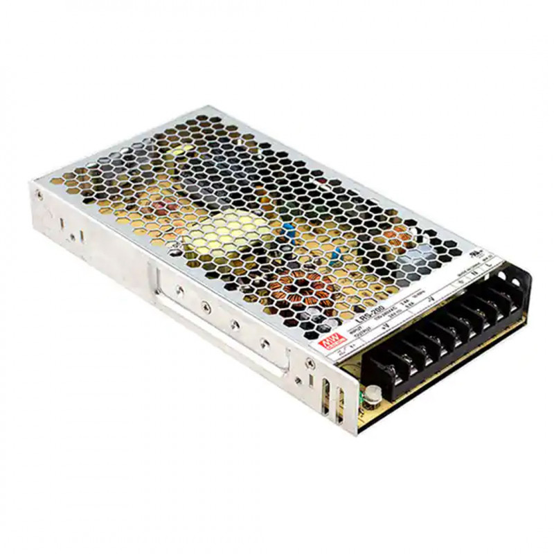
- Mean Well power supply: choosing a quality power supply is one of the main points of getting a reliable printer. Available in different wattages to suit your needs.
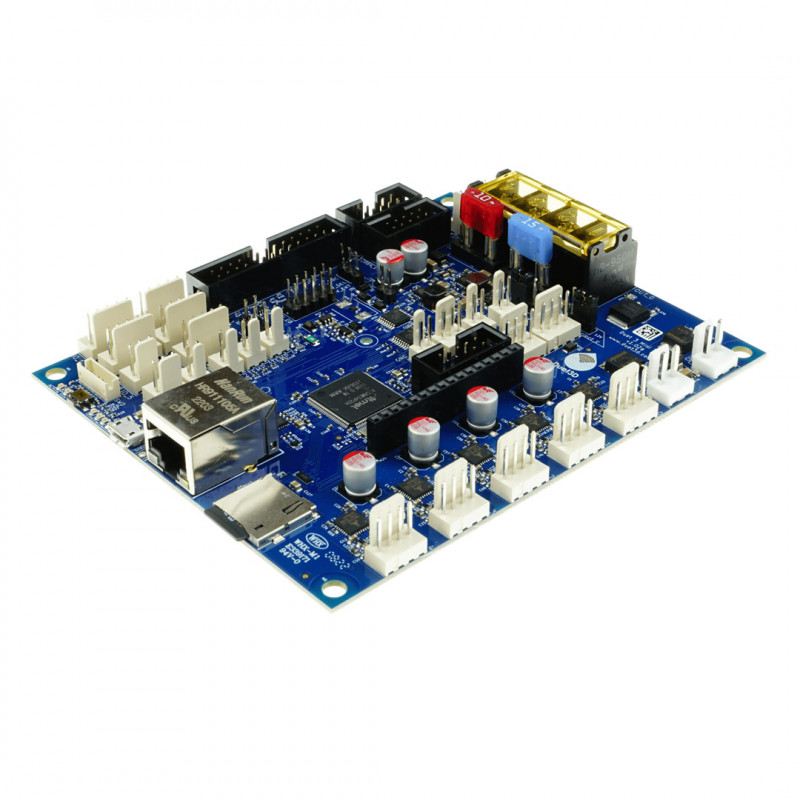
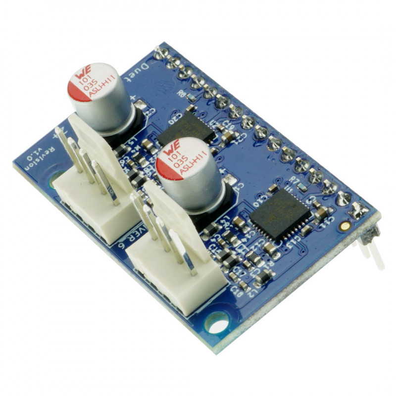
- Duet Mini5+: 32bit Duet3D control board with high-speed bus. It is a board that balances value and performance. It allows you to manage motors, fans, heaters, screen and more. Available in Ethernet and Wifi versions.
- Duet Mini2+: expansion to pair with Mini5+ to connect up to 7 motors managed by driver Trinamic 2209 (up to 1.4 A RMS and 2 A peak).
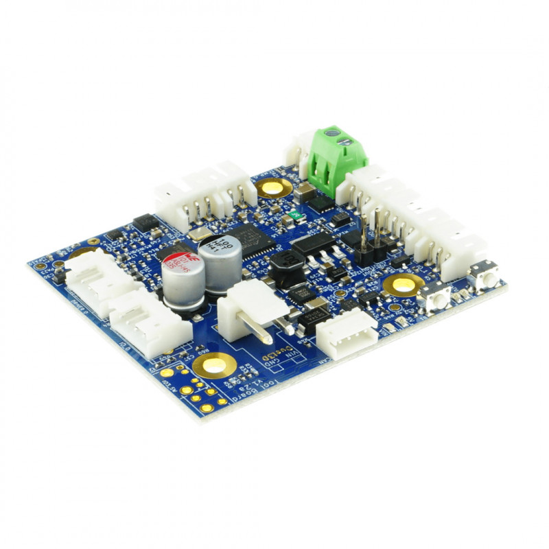
- Duet 1LC: allows via BUS complete control of the extruder assembly (Afterburner or Stealthburner): the entire wiring is reduced to 4 wires. It manages stepper motor, heater, temperature sensors, fans, z-probe and filament sensor. An important feature is the built-in accelerometer that enables vibration analysis and removal along the axes.
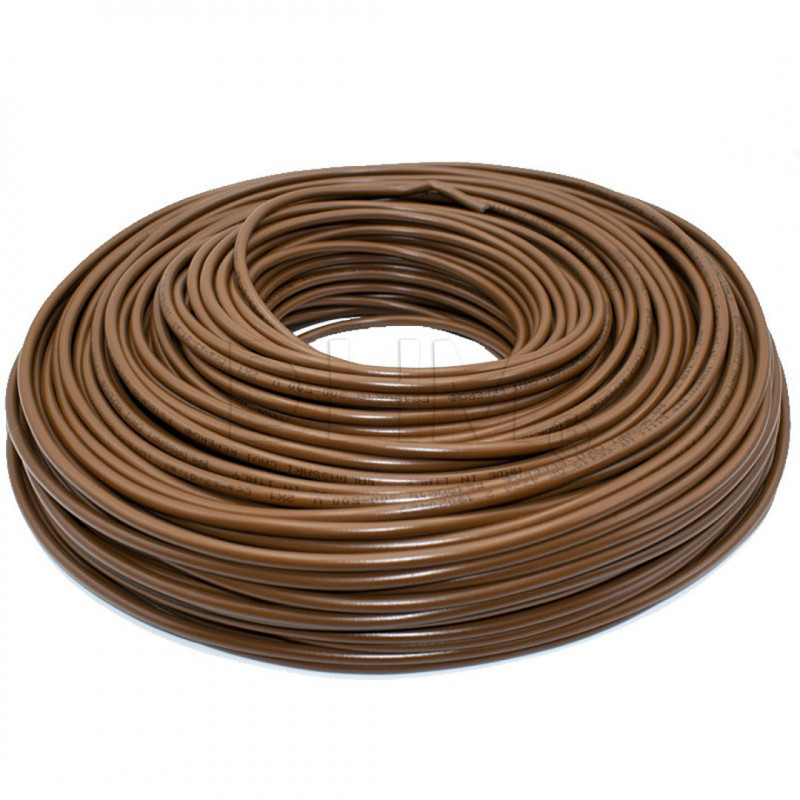
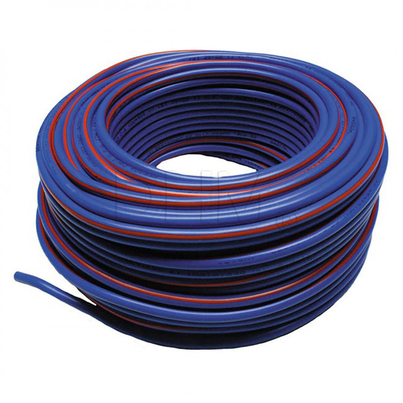
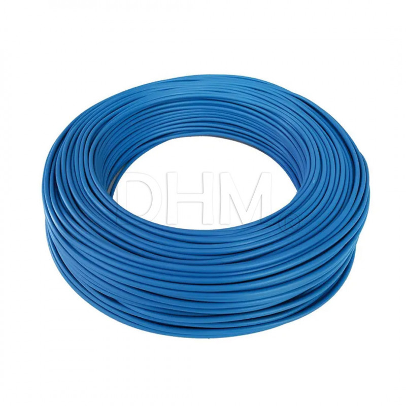
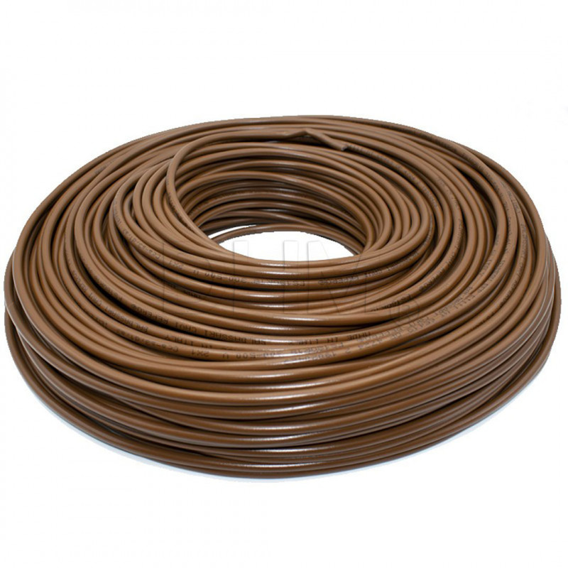
- Made in Italy cables: flexible multi-core FROR cables for power, signal and control transmission. Supplied sized according to the specific application. They are PVC insulated and PVC sheathed. The main characteristics of FROR cables are: non-propagation of flame, non-propagation of fire, reduced emission of smoke, toxic and corrosive gases. Due to their flexibility, they can also be laid in gland chains.
- RS 485 1x2x22/7AWG shielded BUS cable: for connecting the 1LC to the control board. This is a 2-wire shielded BUS cable.
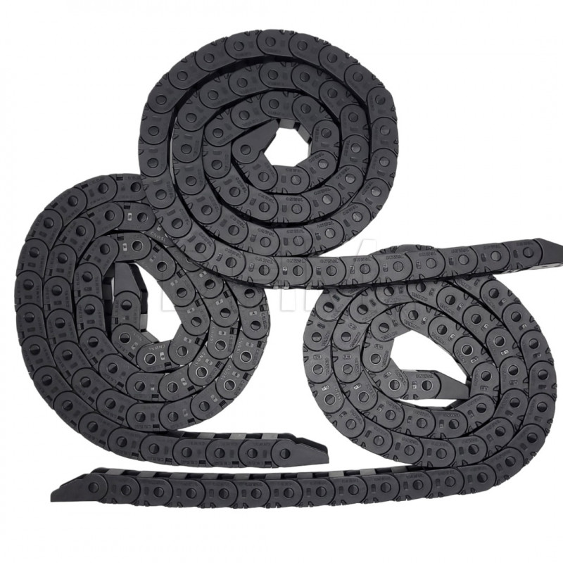
- Cable chains: the supplied chains have a bending radius of 18 mm. This allows them to be installed in a small space. The peculiarities of these chains are: snap opening in the outer side, 3-hole attachment, modular configurable length--they can be shortened or lengthened by removing or adding links, cable protection given by smooth finish, sturdy, easy to assemble, small dimensions in height and pitch, quiet operation due to small pitch.
- Duet Rotating magnet: the rotating magnet filament end sensor from Duet3D can also be included in the kit. This is a filament sensor that allows continuous flow monitoring with sampling every 40ms. This allows real-time interception of, for example, any clogging of thehot end or extrusion system under stress (first layer too flattened, over-extrusions, exceeding volumetric flow rate hot end). It pauses the print allowing the operator to intervene and save it.
- PanelDue 7i (Duet3D): the screen is an on-board help for various reasons, e.g., filament loading/unloading operations, preheating, printing startup. The printer with control board Duet3D, however, can also be controlled without a screen. In fact, the web-interface Duet3D can be used . this is an interface that can be managed directly from a browser that allows control of the machine via wifi or ethernet in the same network. It can also be managed remotely with appropriate customizations.
Note for assembly
- When wiring the machine, it will be necessary to tilt the machine several times to pass the cables from the electronics compartment at the bottom, to the print booth at the top. Be careful: clamping the XY axes with cable ties can help to avoid damage.
- As a first step, the space available on the DIN bars already installed in the part below the printer should be organized. The space, given the size of the base, will be exact for the 250mm model, while it will be abundant for the 350mm model. We therefore recommend placing all the various components, securing them with the appropriate brackets and then moving on to the wiring.
- Special attention should be paid to the crimping of the terminals. In particular, the JSTs on the Duet3 1LC board are particularly small and you need to equip yourself with suitable pliers in case they are not already available to you. You may possibly find them on our website in the dedicated section.
Note for wiring
The order to follow for proper wiring of the printer Voron 2.4 is as follows:
- Prepare the cables crimped on one side only.
- Wire all components of theAfterburner (or Stealthburner) to the 1LC board.
- Begin laying the BUS cable and power cable for the extruder assembly in the X-axis chain.
- Once the Y-axis is reached, also insert the limit switch cable into the Y-axis chain and proceed to the back of the machine near the B-motor.
- Run the cables down the chain along the Z axis. In case there is not enough room for the A motor cable you can leave it external by securing it with cable ties. By using double-sheathed cables to ensure better performance over time, the chain space in some cases is restricted if the cables are not arranged properly. We did not change the section of the chains provided by the design Voron because this would reduce the printing area. By using double-sheathed cables such as those provided, there is no problem even if installed outside the chains.
- Pass through the hole in the bottom of the deck panel. Flip the chassis over and run through the wireways to reach the plugs on the control board.
- Having reached this point it is necessary to wire the board. We recommend checking the wiring diagram of the Duet Mini5+ board, or other board to be mounted, to avoid making mistakes. Then position the cables to size: you can keep the excess cable in the wireways, or you can cut them to size, and then crimp them.
- Connect the control cables to the board, the DC power cables to the power supply, the AC cables to the heated floor (remember the ground connection), and so on. Follow the directions described in the enclosed manual, where you will also find sample pictures.
- Before turning on the printer, carefully reverify the entire wiring below and above. This prevents possible damage!
- Before starting the printer Voron 2.4 you will need to load the firmware in order to print. If you are not used to using Duet you can consult the official documentation for the first startup of the board. Find all the details here: https://docs.duet3d.com/Duet3D_hardware/Duet_3_family/Duet_3_Mini_5+_Hardware_Overview
- Compiling firmware by hand can be complicated. For this reason, we recommend using RepRapFirmware Configuration Tool to set up the initial configuration of the machine. This tool will create a series of files to put on the SD card, including config.g and system macros for homing, probing, pausing, resuming, and canceling. Details here:
https://docs.duet3d.com/en/How_to_guides/Configuring_firmware
https://configtool.reprapfirmware.org/Start
- You can then customize the firmware as needed. Alternatively, you can optionally choose a pre-set firmware to load without difficulty.
For more specifics you can consult our BLOG, where you will find dedicated guides:
https://www.dhm-online.com/en/blog/printers-3d-voron-design-c13
Safety note.
All wiring and electronic components are of the highest quality. However, if the wiring is not done professionally, paying attention to crimping, running the cables in the proper wireways, and connecting them correctly, problems can occur. Depending on skill level, then, it may be helpful to practice crimping and soldering before wiring everything up. Wrong crimps are a major source of problems with a running machine and are sometimes difficult to identify!
When wiring the electronic components of the printer Voron 2.4, you are working with mains voltage (220V AC) wires. Before touching any wires or terminals, always check that the printer is unplugged and that the capacitors in the power supplies have discharged.
The Duet Mini5+ board already provides fuses on the DC power outputs, there is also an AC fuse in the upstream power inlet. A DC fuse can possibly be added to the power line of the 1LC board to isolate, in case of malfunction, the printhead from the rest of the machine.
Better to abound in caution than to generate damage.
Never connect or disconnect any device while the printer is powered. Besides being a safety hazard, it is very easy to damage electronic components. In particular, the driver stepper motors can be easily damaged by connecting or disconnecting them while they are powered.
Voron 2.4: an introduction
The Voron 2.4 is a motion 3D printer design CoreXY with a fixed plane designed by Voron Design. This printer is known for its reliability and high performance.
Staying true to the fundamentals of the RepRap project, the Voron 2.4 is completely open-source, customizable and self-buildable.
The DHM kits of Voron 2.4 were born out of the need to gather the various requests of our customers: from those who struggle to find the material to those who have pointed out gaps and critical points in the kits already commercially available. The DHM kits are born from our experience in the 3D printing industry and knowledge of quality manufacturers. In addition, thanks to our in-house workshop, we have created custom components by making design improvements to give optimal reliability and performance.
The DHM kits from Voron 2.4 are currently available in 3 main variants that differ only in the size of the build space:
- Kit Voron 2.4 250 mm → 250x250x250 mm
- Kit Voron 2.4 300 mm → 300x300x300 mm
- Kit Voron 2.4 350 mm → 350x350x350 mm
There is the possibility of some customization in some step of the kit, such as the choice of the extruder or the choice of the control board.
Do you want to build your own 3D printer Voron 2.4?
Our step-by-step kits for Voron 2.4 include 9 step + one optional tenth. In each step you will find the components for assembly accompanied by a manual with construction instructions and cautions.
We decided to divide the construction of Voron 2.4 into several steps to facilitate the assembly moments and also to allow for deferred purchase over time. We aim for quality and reliability of components rather than offering a cheap or incomplete kit.
Why buy a Voron 2.4 kit?
Owners of the Voron 2.4 praise it for its reliability and speed. Buying a kit printer allows you to customize various points: from the appearance, to the choice of size, type of electronics, extruder, and many others.
The Voron 2.4 DHM kit approach is to STEP: a step-by-step approach to building, each in his or her own time, a printer Voron. Each step has everything you need to finish that specific part of assembly, and this allows you to be able to pause the project and resume it without particular difficulty.
We have broken down and customized some of the steps in the official guide Voron into specific manuals for each step downloadable PDF. You will thus find step-by-step support for assembly. The manual for this step is available in the "Attachments" section of this page.
Check out our BLOG: https://www.dhm-online.com/en/blog/printers-3d-voron-design-c13
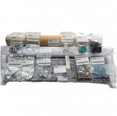
The kit contains (BOM STEP 8 V2.4):
1 x LRS 200 24 AC/DC CONVERTER 24V 211W MEAN WELL power supply.
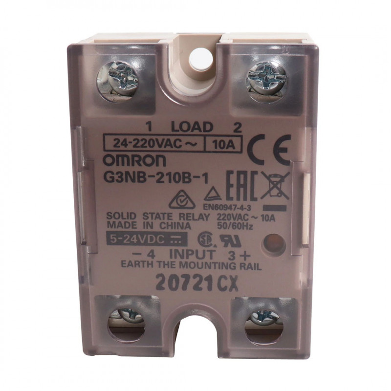
1 x Fotek SSR 40 DA Solid State Relay
1 x Duet 3 Mini 5+ Ethernet
1 x Duet 3 Expansion Mini 2+
1 x Duet 3 Toolboard 1LC
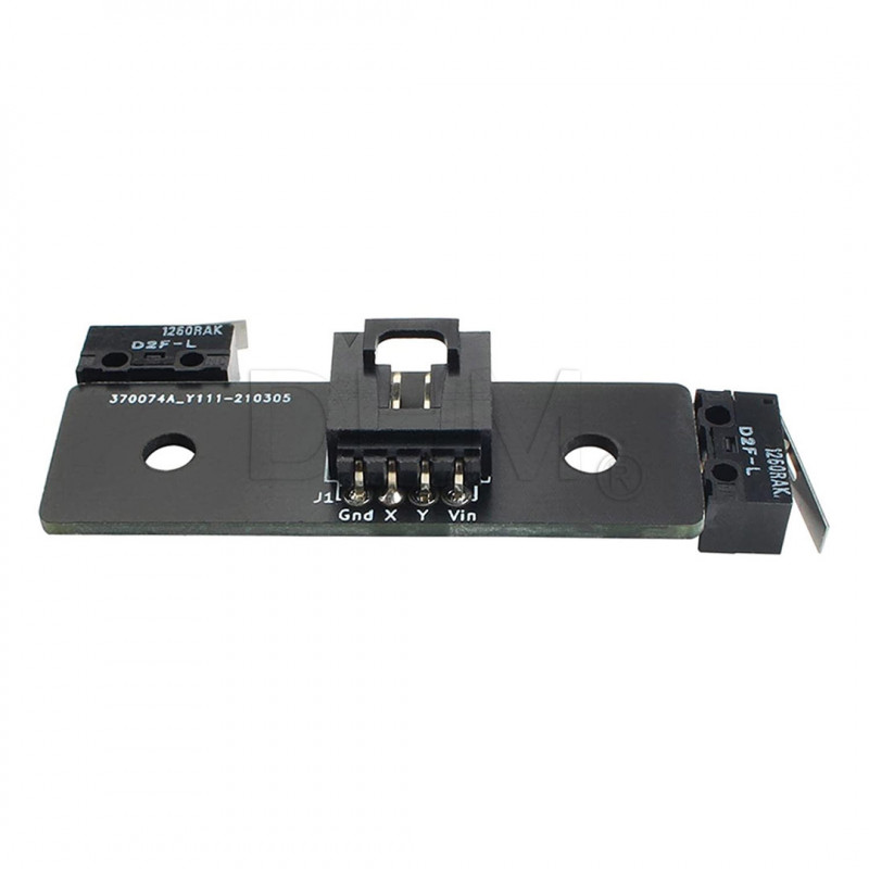
1 x X/Y Microswitch Endstop PCB
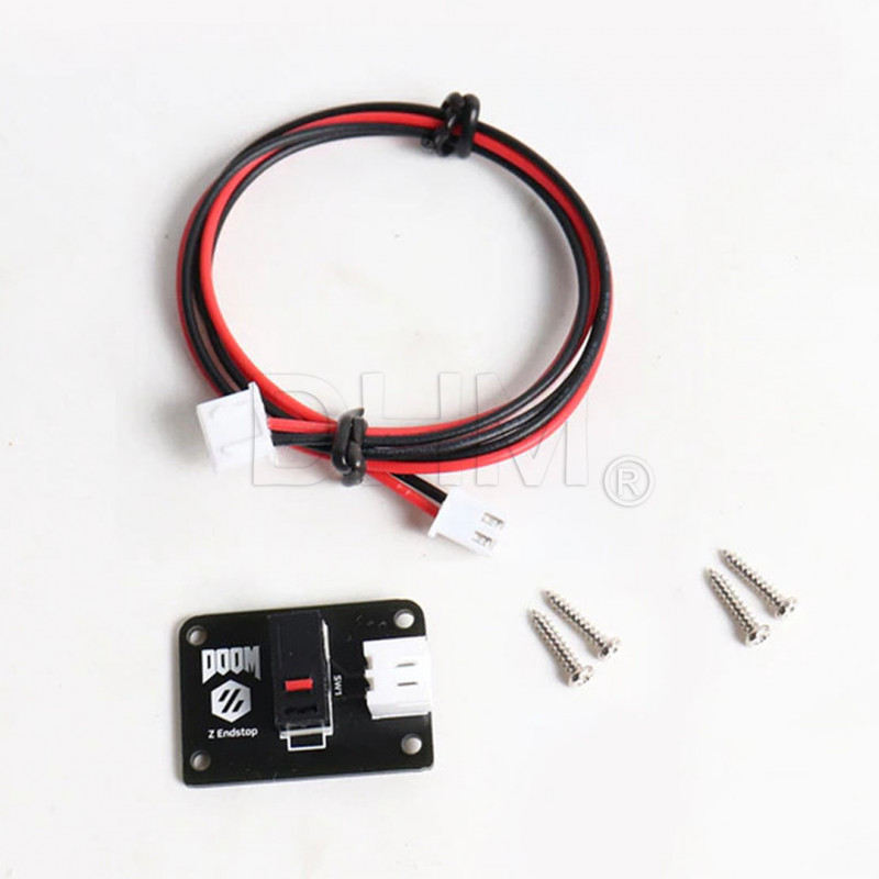
1 x Z-axis endstop PCB with 40cm cable
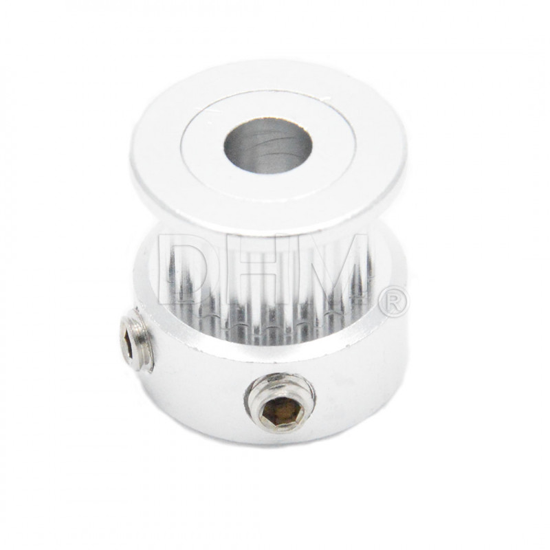
1 x GT2 Pulley Ø 5mm 20 teeth H6
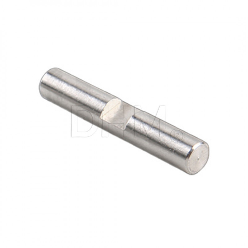
1 x Hardened and ground shaft Ø 5mm x 30mm
3 x Shielded BUS cable for RS 485 electronic devices 1x222/7AWG
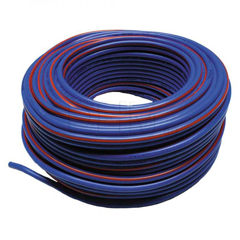
4 x FROR BLUE EXTERNAL CABLE 2x0.5 per meter
2 x FROR BLUE CABLE FOR OUTDOOR 4x0.5 per meter
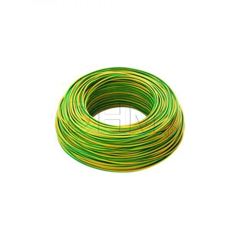
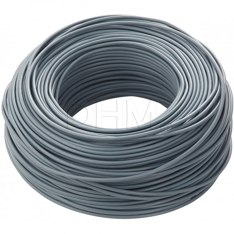
1 x FS17 CABLE 1 GV ROPE FS17 1X2.5 G/V per meter
1 x FS17 450/750V BLUE CABLE 1x2.5 mm per meter
1 x FS17 Cable 450/750V BROWN 1x2.5 mm per meter
1 x FS18 CABLE 2X2.5 300/500V CPR C BROWN by the meter
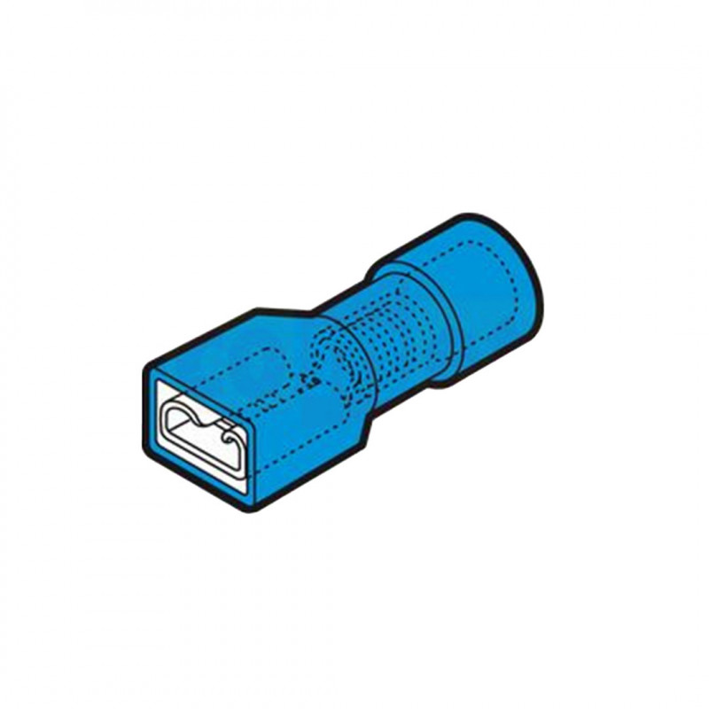
10 x FEMALE FEMALE FASTON CONNECTOR
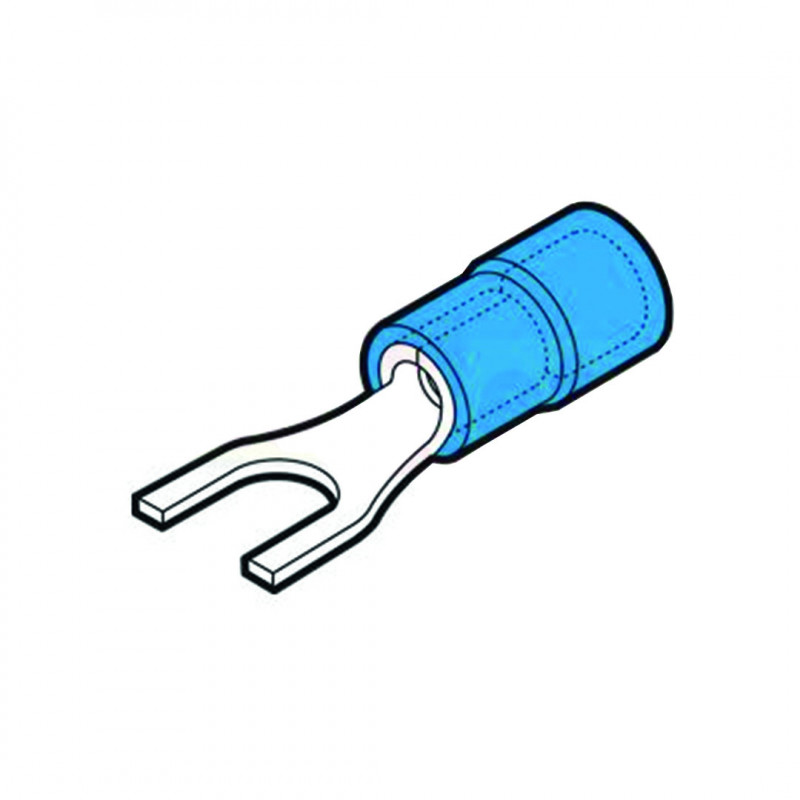
20 x BLUE FORK COIL 4mm screw
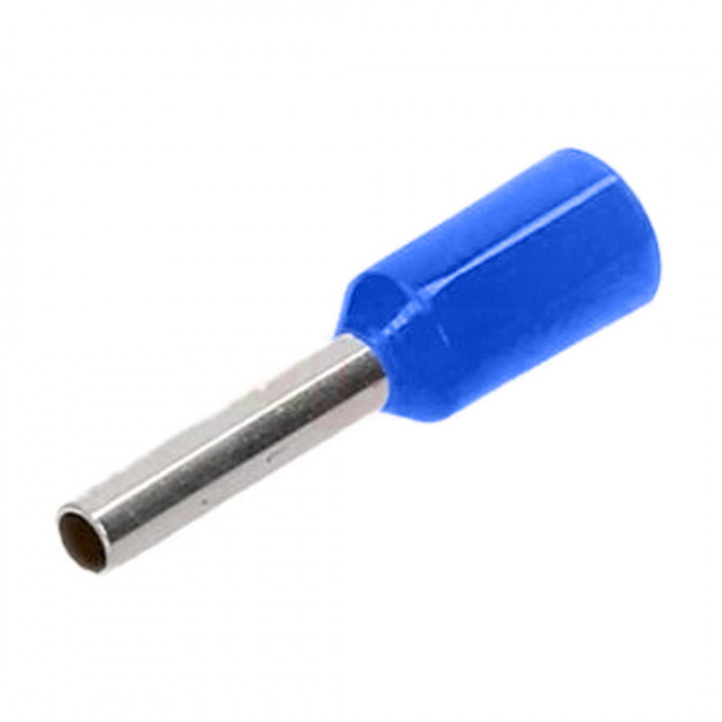
15 x PRE-INSULATED TERMINAL TUBE 2.5mmq P 8mm BLUE
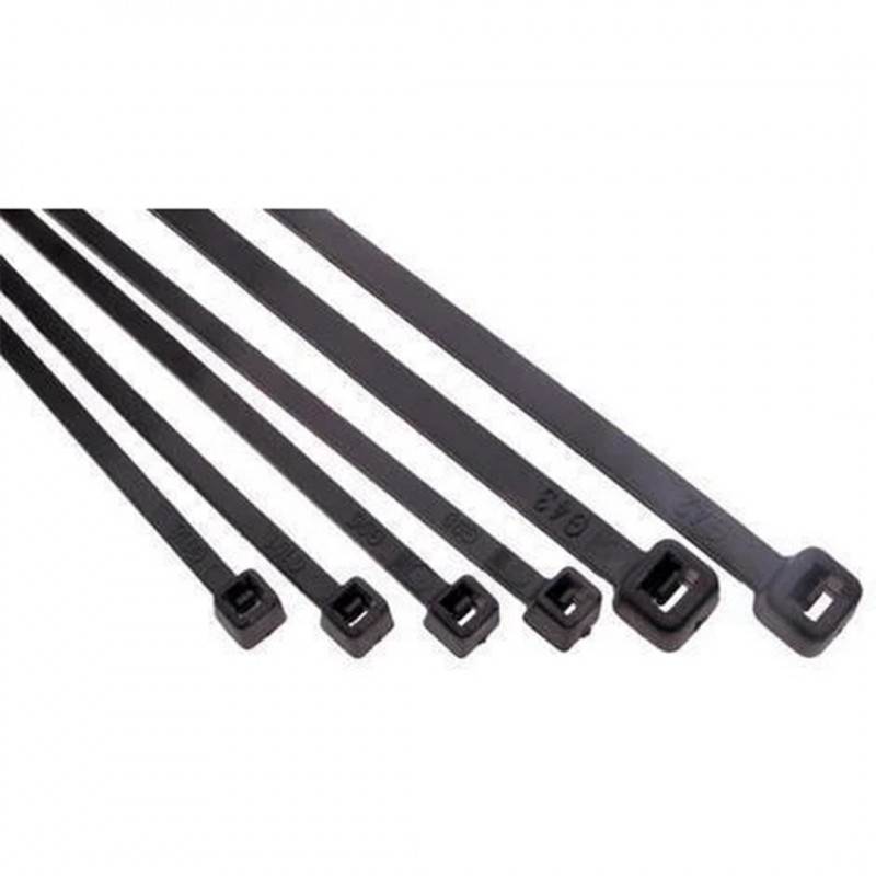
20 x Black nylon cable tie 100x2.5 mm
1 x Heat-shrinkable shrink tubing
1 x DHMpro cable chain kit 1 piece 15x10 + 2 pieces 10x10 with external opening
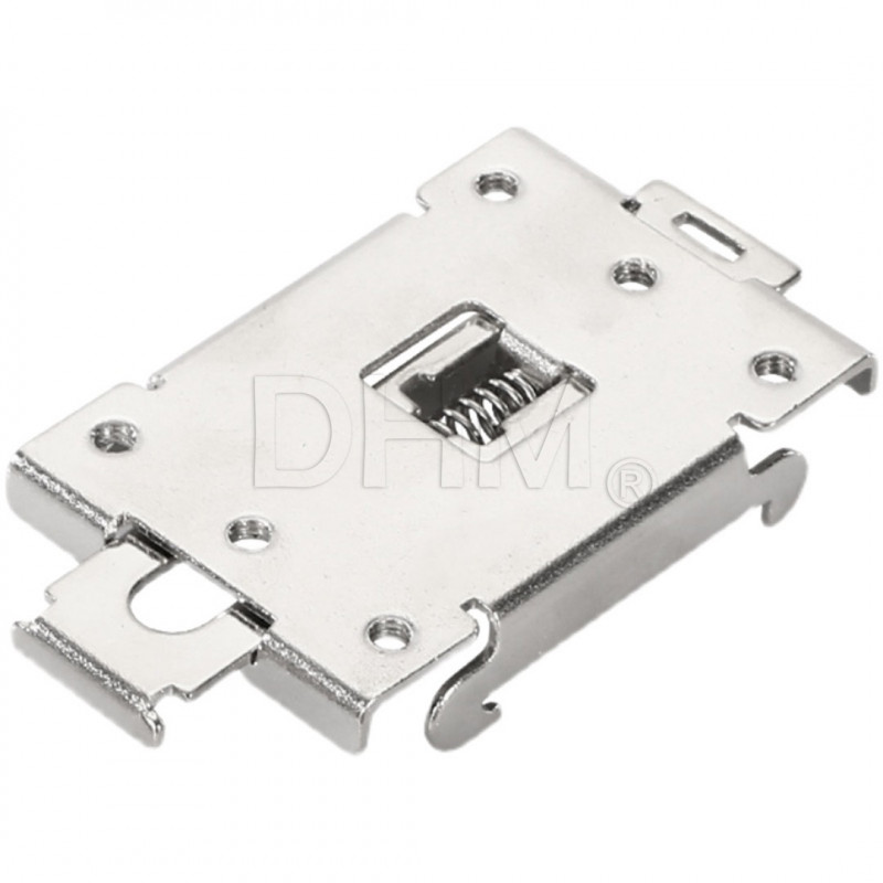
1 x Support bracket for G3A SSR relay on DIN rail
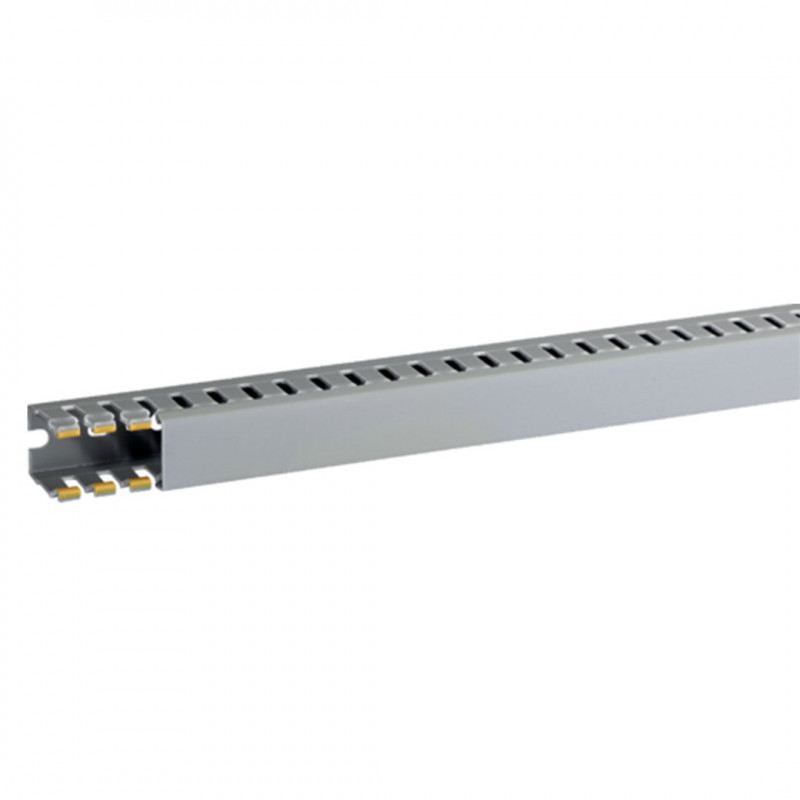
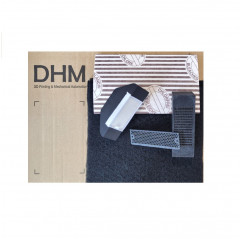
2 x Channel with slots for cable routing with cover
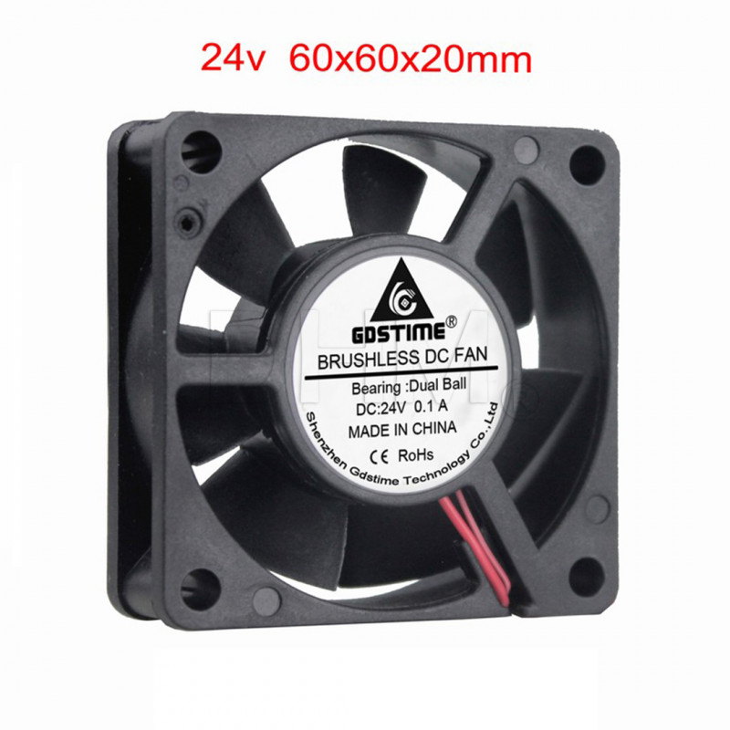
2 x Double bearing fan 60x60x20mm 24V
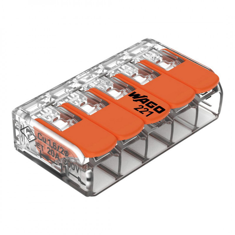
3 x Wago 5-position compact lever junction connector
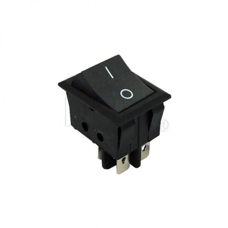
1 x Rocker switch 16A 250V /125V BLACK
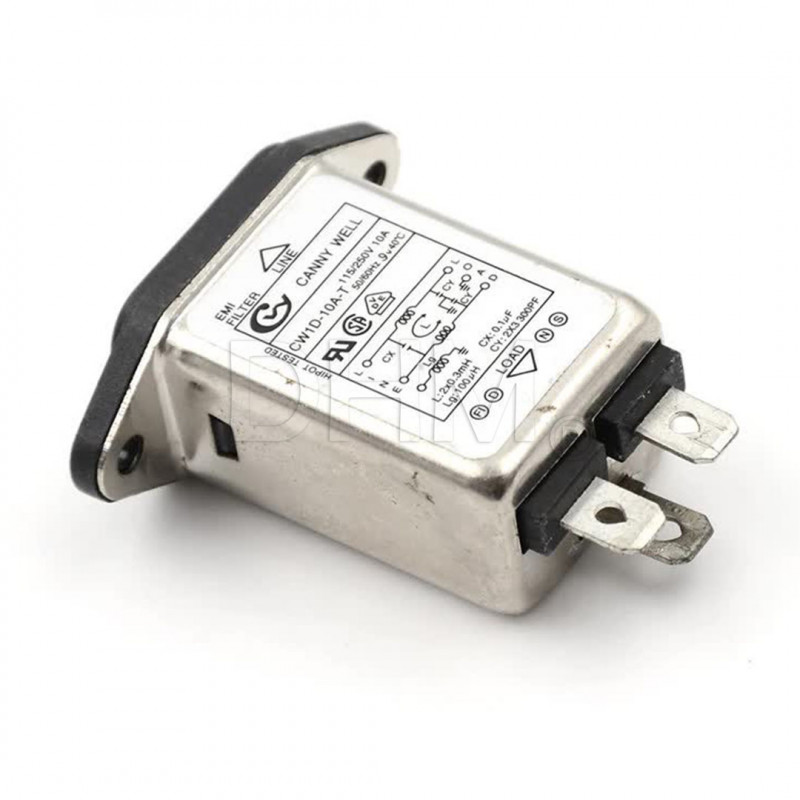
1 x AC power input module: socket + YB11 B2 filter + fuse
13 x M3 galvanized hex nut
2 x M4 galvanized self-locking nut
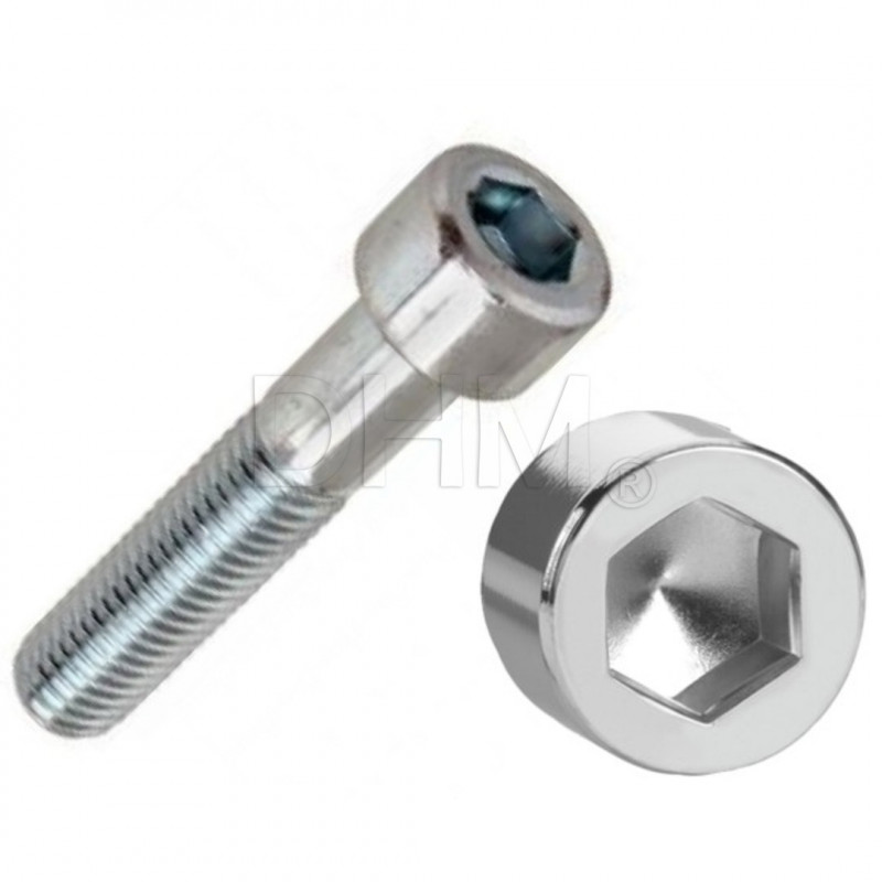
2 x Galvanized 5x12 socket head screw with Allen recess
2 x Screw 4x14 cylindrical head with cross recess galvanized
35 x Screw 3x8 cylindrical head with Allen recess galvanized
4 x Screw 3x12 cylindrical head with Allen recess galvanized
8 x Screw 3x16 cylindrical head with Allen recess galvanized
4 x Screw 3x20 cylindrical head with Allen recess galvanized
2 x 3x30 Cylinder head screw with galvanized socket recess
8 x Galvanized 3x6 countersunk flat head screw with Allen recess
4 x Countersunk flat head screw with galvanized socket recess 3x10
5 x Cylinder head countersunk screw with galvanized socket recess 4x6
7 x 5x10 rounded cylindrical head screw with galvanized socket recess
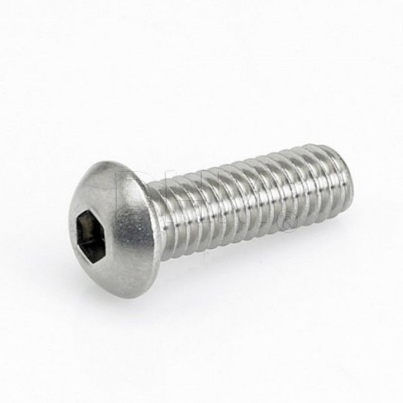
4 x 3x16 rounded cylindrical head screw with stainless socket recess
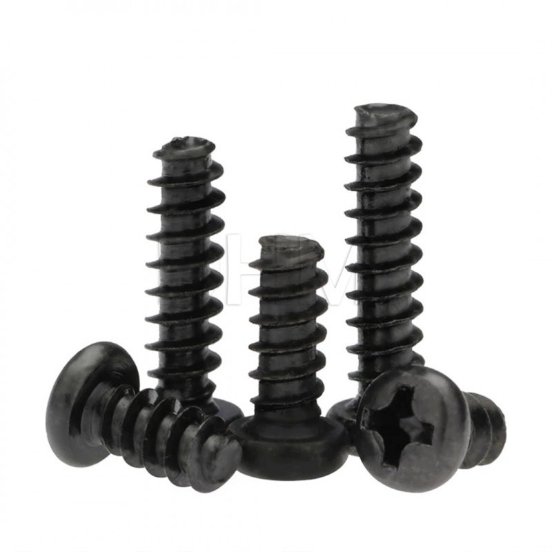
4 x Self-tapping black 2x10 cross recessed cylindrical head screw (for duet fastening support plastics)
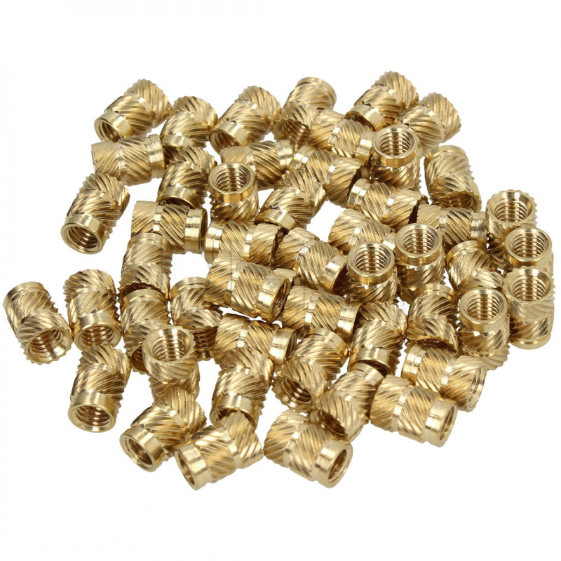
28 x Brass threaded insert M3 - 3x4x5 mm
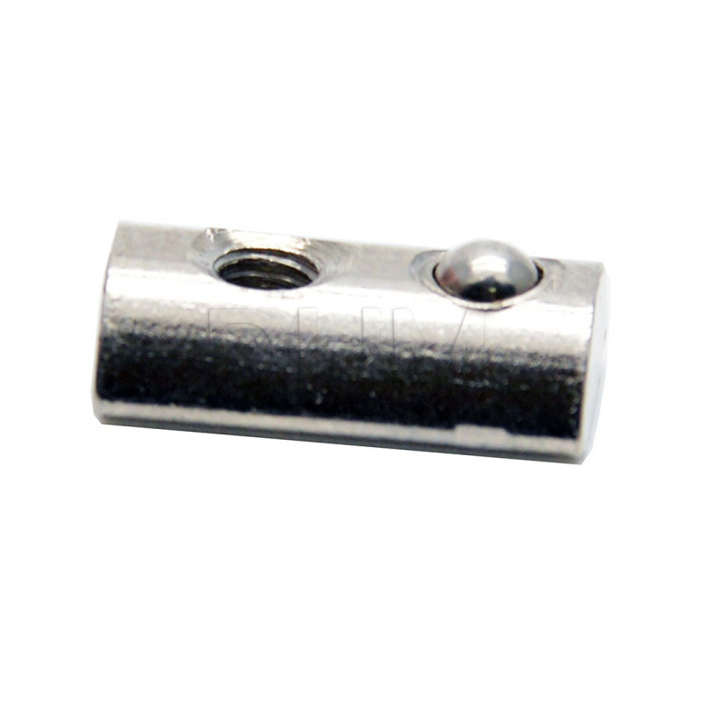
8 x Nut with spring for post-assembly - Series 5 steel - M3 thread
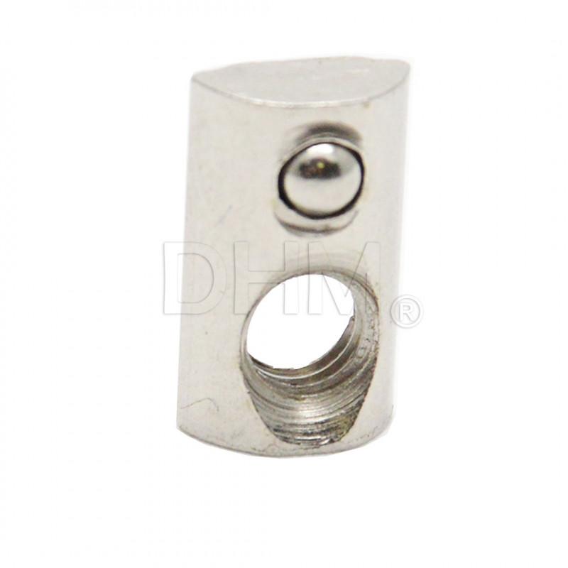
9 x Nut with spring for post-assembly - Series 5 steel - M5 thread
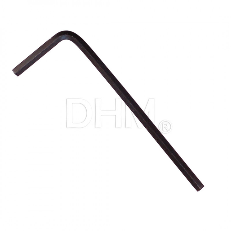
1 x Allen wrench 2 mm ISO 2936 DIN 911 galvanized steel allen key
1 x Allen key 2.5 mm ISO 2936 DIN 911 galvanized steel allen key
1 x Allen key 3 mm ISO 2936 DIN 911 galvanized steel allen key
OPTIONAL
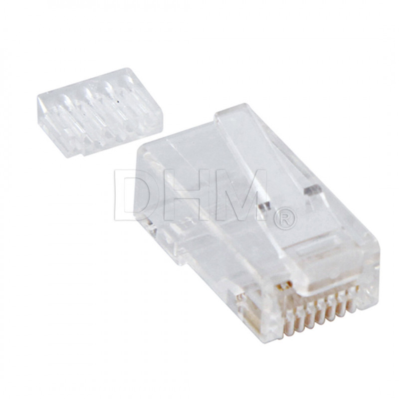
1 x Pre-wired ethernet cable (complete with cable and board side RJ45 socket and female panel socket for LAN connection)
1 x Duet3D Filament Monitor Rotating Magnet filament sensor
1 x Duet3D PanelDue Integrated 7
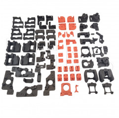
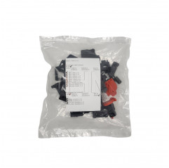
1 x Plastic Kit step 8
Check out related products for STEP next and earlier!


